▶ MAIN FEATURE
●Heading Accuracy: 0.5°
●Roll Measure Range:±180°
●Tilt Resolution: 0.1°
●Tilt Accuracy: <0.2°(Full Range)
●Working Temp.: -40℃~+85℃
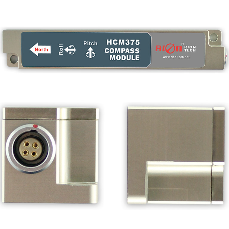
●Dimension: L110×W19.5×H19.5mm
●With Hard And Soft Magnetic Calibration
●Rs232/Rs485/Ttl Output
▶ APPLICATION
● Satellite antenna search satellite
● Marine navigation surveying and mapping
● GPS integrated navigation
● Antenna servo control
● Gun emission system
● Infrared imager
● Laser range finder
● Map for plotter
● ROV underwater robot navigation
● Oceanography measurement instruments
● Special occasion robot
● Unmanned aircraft
HCM370B-HCM375B integrated patented three -axis flux-gate technology. It calculates heading value in real-time by CUP,
and perform heading value compensation in wide tilt range by using three axis accelerometer. It is high performance and
excellent stability militarily level compass sensor. Its volume is small, power consumption is low. It could widely used in
many application such as antenna installation, vehicle and integrated system, and so on.
| HCM370B / HCM375B Index | ||
| Heading | Heading Accuracy | 0.5° Tilt < 10° |
| 2.0° Tilt < 60° | ||
| 3.0° Tilt < 80° | ||
| Resolution | 0.1° | |
| Tilt | Pitch Accuracy | 0.1°<15° (Measure Range) |
| 0.1°<30°(Measure Range) | ||
| 0.1°<60°(Measure Range) | ||
| 0.2°<85°(Measure Range) | ||
| Pitch Range | ±85° | |
| Roll Accuracy | 0.1°<15°(Measure Range) | |
| 0.1°<30°(Measure Range) | ||
| 0.1°<60°(Measure Range) | ||
| 0.2°<180°(Measure Range) | ||
| Roll Range | ±180° | |
| Resolution | 0.1° | |
| Calibration | Hard Magnetic Calibration | Available |
| Soft Magnetic Calibration | Available | |
| Magnetic Filed Interference Calibration Method |
Rotate 360° Horizontally; Vertical Rotation(Optional) |
|
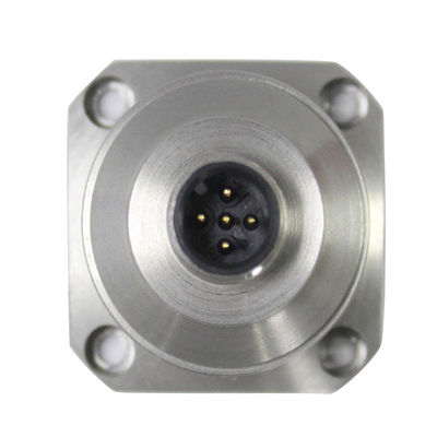
| RS-232/RS485/TTL | 5Pin Quick Plug Connector | |
| Interface | Start Delay | <50ms |
| Max Output Rate | 20Hz/s | |
| Communication Rate | 2400 TO 19200baud | |
| Output Format | Binary High Performance Protocol | |
| Power Supply | Power Voltage | (Default)DC+5V |
| Current(Max) | 30ma | |
| Ideal Current | 26ma | |
| Sleep Mode | TBD | |
| Environment | Working Temp. | -40℃~+85℃ |
| Storage Temp. | -40℃~+100℃ | |
| Anti-Shock Performance | 100g | |
| Protection Level | IP67 | |
| Electromagnetic Compatibility | According TO EN61000 and BT17626 | |
| Mtbf | ≥40000 Hour/Time | |
| Insulation Resistance | ≥100M.O. | |
| Anit-Impact | 100g@11ms,3Times/Axis(Half Sinusoid) | |
| Anti--Shock | 10grms,10~1000Hz | |
| Dimension | L110×W19.5×H19.5mm | |
| Weight | 70g(Not Include Cable) | |
▶ MEASURING DIRECTIONS&FIX
HCM370B-HCM375B 3D electronic compass azimuth is using geomagnetic principle, so it is very important to select a minimum magnetic interference environment for installation positon. Please place and install the it away from the iron, magnets, engines and other magnetic objects as much possible as you can. Need control over 30CM distance(different magnetic interfere with the compass in different distance ) at least even there are these magnetic medium around . In order to ensure optimal measurement environment please must use the M3 anti-interference screws for installation .
Although it can compensate the moderate deviation in the stable magnetic environment, but it can not compensate the changed magnetic interference. Please pay much attention to the wire with DC will generates a magnetic field , because if the DC change then the magnetic field will also change in size . The battery also is another interference source of changing . Each installation is different, and the user must evaluate the feasibility of installation under all possible operating environment.
The optimal heading accuracy of it can reach 0.3°~0.5°, this undergo a rigorous validation indisputable, the most scientific test method is equally crucial. The test method we recommend is: Please install the electronic compass to a vertical and erect aluminum pole (non-magnetic material), then proceed with heading accuracy measurement (of course the rotating rod perpendicular to the rotating platform, as much as possible to avoid large external magnetic field interference). Doing so can reduce the compass turning radius, to scientifically improve the measurement accuracy. This is just to provide the installation of the laboratory, must be flexible to deal with the specific situation.E.g: is mounted in the car, HCM505B should do its installation in the perpendicular to the movement direction.