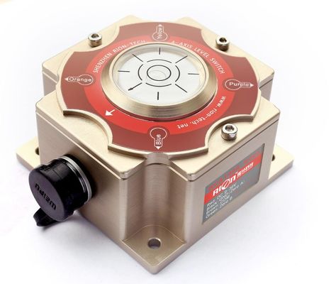

IMU570 inertial navigation unit is composed of three-axis gyroscope, three-axis acceleration, temperature sensor and signal processing circuit. The three-axis angular rate of the carrier is measured, and the three angular rate data after error compensation (including temperature compensation, installation misalignment compensation, non-linear compensation, etc.) are output through RS422 serial port according to the agreed communication protocol. The product adopts differential gyroscope structure, effectively restrains the influence of linear acceleration and vibration, and adopts full temperature compensation to suit the harsh environment of industrial application.
Feature
★ measure triaxial angular velocity of carrier ★ working temperature:-40~85℃
★ storage temperature :-40~85℃ ★ Vibration:10~2000Hz,10g
★ power supply :+5±0.5V(DC) ★ impact:100g@11ms,Triaxial (half sinusoidal)
★ Autopilot Vehicle ★ Unmanned Aerial Vehicle ★AGV
★ SOTM attitude unit ★ POS System for Surveying and Mapping
★ Ship and Marine Engineering ★ Ocean and Underwater Surveying and Mapping
★ Flight Control System ★ High Speed Train Measurement and Control System
![]()
|
IMU570
|
|
|
Parameters
|
|
||||
|
GYRO
|
|
|
|
|
||||
|
Measuring range
|
|
|
1800°/s
|
|
||||
|
Zero bias instability(@Allan variance)
|
|
|
≤8°/h(-20~70 ℃)
|
|
||||
|
angle random walk(@Allan variance)
|
|
|
≤0.13°/√h & 0.24°/√h
|
|
||||
|
Zero Bias Acceleration Sensitivity
|
|
|
≤1°/h/g
|
|
||||
|
Resolution
|
|
|
≤0.001°/s
|
|
||||
|
Scale factor nonlinearity
|
|
|
≤100ppm
|
|
||||
|
Scale factor repeatability
|
|
|
≤100ppm
|
|
||||
|
Cross-coupling
|
|
|
≤0.1%
|
|
||||
|
Bandwidth
|
|
|
≥200Hz
|
|
||||
|
Accelerometer
|
|
|
|
|
||||
|
Measuring range
|
|
|
±38g
|
|
||||
|
Zero bias instability(@Allan variance)
|
|
|
0.019mg
|
|
||||
|
Zero bias repeatability
|
|
|
0.08mg
|
|
||||
|
Speed random walk(@Allan variance)
|
|
|
0.04m/s/√h
|
|
||||
|
Zero Bias Error in Full Temperature Range
|
|
|
0.5mg
|
|
||||
|
Weight
|
|
|
(52±5)g
|
|
||||
|
Other parameters
|
|
|
|
|
||||
|
Power supply voltage
|
|
|
(+5±0.5)V(DC)
|
|
||||
|
Power supply Current
|
|
|
Working current<0.3A
|
|
||||
|
Working temperature
|
|
|
-40~85℃
|
|
||||
|
Storage temperature
|
|
|
-40~85℃
|
|
||||
|
Vibration
|
|
|
10~2000Hz,10g
|
|
||||
|
Impact
|
|
|
100g@11ms,Triaxial (half sinusoidal))
|
|
||||
|
|
|
|
|
|
||||
Note:
integrated inertial navigation system has not this configuration and needs to be suspended.
External trigger sources need to be specially configured according to requirements. The default IMU integrated inertial navigation system has not this configuration and needs to be suspended.
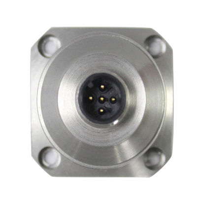
IMU570 contains three DOF gyroscopes, representing three axes of spatial coordinate system, namely X, Y and Z. The X axis positive is directed forward from the connector to the middle mounting hole of the sticker, the Y axis positive is directed right to the IMU, and the Z axis positive is directed downward to the bottom of the IMU, as shown in Figure 1.